Mohamed Aziz Lassoued

Explore my projects and technical work.
Electrical Automation Engineer
About
Welcome to my portfolio, where i showcase my work as an Electrical Automation Engineer. Passionate about PCB design, embedded systems, and IoT-based industrial solutions. I am seeking a full-time role in hardware design.
- Email: lassoued10.mohamedaziz@gmail.com
- LinkedIn: Mohamed Aziz Lassoued
- GitHub: med-aziz1
- Phone: +216 25 333 669
Technical Skills
- Design Tools:
- Altium Designer, Saturn PCB Toolkit, Proteus, ModelSim, LabVIEW, Simulink
- Programming Languages:
- C/C++, Python, Assembler, Java, Dart, MATLAB, VHDL
- Software and IDEs:
- STM32CubeIDE, Visual Studio Code, Arduino IDE, TIA Portal, Android Studio, Google Colab
- Communication Protocols:
- UART, I2C, SPI, CAN, MQTT, HTTP
- Microcontrollers/Microprocessors:
- STM32, ESP32, Raspberry Pi, Arduino, MSP430
- Development Frameworks and Debugging Tools:
- FreeRTOS, ESP-IDF, Git, JTAG/SWD, OpenOCD
Education
- National Engineering School of Gabes (ENIG), Electrical and Automation Engineering
September 2022 - June 2025 - Preparatory Institute for Engineering Studies (IPEI Gabes), Preparatory Cycle
September 2019 - June 2022 - Sombat High School, Science Technology Baccalaureate
June 2019
Experience
4InA Technologie, Manouba | End-of-Year Internship
February 2025 - June 2025
- Designed a 4-layer PCB integrating STM32 and ESP32 microcontrollers for a modular smart meter.
- Developed embedded firmware for data transmission and remote control via an HTTP server.
- Delivered a functional prototype for industrial use.
- Keywords: Embedded Hardware, 4-layer PCB, DFM, Altium Designer, Smart Meters
WEMAKE 3D, Ariana | Summer Internship
June 2024 - July 2024
- Developed a Human-Machine Interface for an automatic cutting device.
- Designed a PCB to interface sensors and motor controls.
- Keywords: HMI, PCB Design, ESP32, Git, 3D Printers
STEG-BTGG, Gabès | Summer Internship
July 2023
- Observed gas compression and pipeline systems, gaining insight into industrial energy infrastructure.
- Keywords: Gas Compression, Pipeline Management, Energy Infrastructure
Projects
Modular Motherboard for Smart Meters
Technologies: STM32, ESP32, LoRa, UART, I2C, SPI, ADC, Altium Designer, Saturn PCB Toolkit, Power Management
Overview
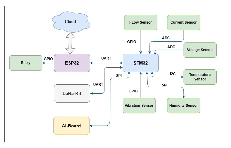
Designed and developed a modular 4-layer PCB for smart metering applications, integrating sensor acquisition, signal processing, and wireless communication. The board supports:
- Current and voltage sensors for real-time energy monitoring
- Interfaces for external sensors such as temperature, vibration, and pressure (via I2C/SPI)
- ESP32 module for wireless control, receiving data via UART from the STM32 core
- LoRa kit for long-range data transmission
- Onboard power regulation (LDO and switching regulators)
- Routing optimized with Saturn PCB Toolkit for impedance control and trace calculations
All design files were created using Altium Designer with careful layer stackup and EMC considerations.
System Block Diagram
A high-level representation of the microcontroller interfaces, sensor inputs, and communication channels.
PCB Design – Gerber Preview
A visual snapshot of the routed PCB, highlighting copper traces, component placement, and ground planes.
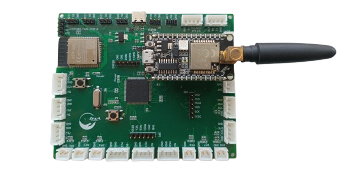
Assembled PCB
Final assembled board used for testing and integration with the smart metering system.
-
Figure 1: Assembled PCB Top View
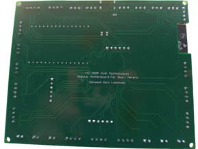
-
Figure 2: Assembled PCB Bottom View
Demonstration – Flashing and Testing
Short demonstration of alimentation testing, firmware upload via ST-Link for STM32, and via USB to UART converter for ESP32.
Applications
- Smart metering systems
- Industrial IoT solutions
Polychaeta PCB
Technologies: ESP32, RFM95W-868S2, Altium Designer, LM2596S, TL1963A, SD Card, MAX485, RS-485, UART, LoRa, IoT
Overview
This is a custom 2-layer PCB designed for remote environmental monitoring and real-time data collection, especially in marine environments. Based on the ESP32 microcontroller, the board interfaces with seven RS-485 sensors to gather data such as salinity, and transmits it to the cloud via LoRa for long-range communication. It also includes local SD card storage as a fallback when internet connectivity is unavailable.
Key Features
- ESP32 bare chip for optimized embedded integration
- RFM95W-868S2 LoRa module for low-power, long-distance wireless communication
- SD card interface for local data logging
- UART to RS-485 (MAX485) module to collect data from 7 industrial-grade sensors
- 12V power input for simplified deployment with:
- LM2596S DC-DC buck converter for stable 5V output (for sensors)
- TL1963A-33 LDO regulator to power ESP32, LoRa, and SD card
- Compact 2-layer PCB layout optimized for modular deployment
Design Details
- Designed using Altium Designer
- Power regulation carefully cascaded to isolate noise-sensitive components (MCU and LoRa)
- Robust connector layout for industrial sensors
- Compact and low-cost form factor optimized for real-world field deployment
Application Context
Part of the Polychaeta Project, this board supports smart environmental monitoring by collecting and analyzing physical parameters in marine or industrial settings. Combined with cloud services and other embedded platforms (e.g., STM32), the system aims to provide autonomous, reliable, and sustainable tools for environmental protection and ecosystem management.
Documentation & Downloads
- Figure 1: PCB Top View

- Figure 2: PCB Bottom View

Documentation & Downloads
-Assembly Files Download PDF
Applications
- Remote environmental monitoring
- Industrial IoT systems with cloud integration
- Data logging in isolated or low-connectivity environments
ESP32-S3 Mini Board Design
Technologies: ESP32-S3-MINI-1, Altium Designer, Saturn PCB Toolkit, CH343, USB-C
Overview
This is a custom 4-layer development board designed around the ESP32-S3-MINI-1 module, inspired by the official Espressif DevKitM-1. The board offers enhanced flexibility with dual USB-C ports, allowing for both power supply and native USB communication independently.
Key Features
- ESP32-S3-MINI-1 module with dual-core Xtensa® LX7 CPU and AI acceleration
- Dual USB-C ports:
- One for native USB (USB-OTG / USB-JTAG / USB-CDC)
- One for power and flashing via onboard CH343 USB-UART bridge
- 4-layer PCB for better signal integrity and noise control
- Onboard 5V to 3.3V LDO voltage regulator
- BOOT and RESET buttons for development and flashing
- Breakout GPIO headers for sensor and module integration
Design Details
- Designed using Altium Designer
- Saturn PCB Toolkit used for controlled impedance and trace width calculations
- USB differential pair routing optimized for signal quality
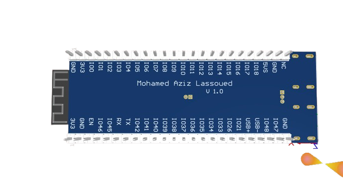
PCB 3D View
- Figure 1: PCB Top View

- Figure 2: PCB Bottom View
Documentation & Downloads
-ESP32-S3-MINI-1 Datasheet Download PDF
-Gerber Files Download ZIP
Applications
- Embedded prototyping
- USB-based device development
- IoT systems using ESP-IDF
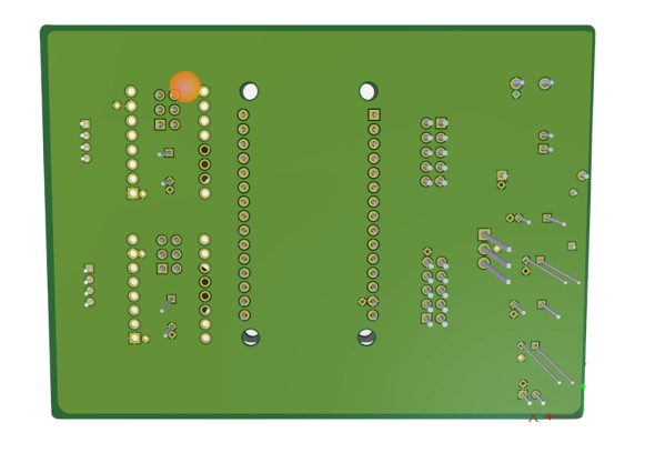
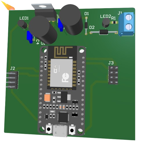
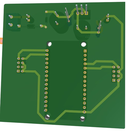
Custom PCB to control the Modular Cutter Device
This is a custom-designed PCB developed for a modular ribbon and belt cutter system. It acts as the main controller board, integrating stepper motor control, LCD interface, and regulated power supply, all centered around the ESP8266 microcontroller.
Key Features
- ESP8266 microcontroller for Wi-Fi-based control and automation
- Dual stepper motor support:
- Cutter motor and feeder motor driven via A4988 stepper drivers
- Output headers provided for clean connection to motors
- RepRap Smart LCD connector:
- For user-friendly HMI control with display and encoder
- Power supply:
- 12V input powering the stepper motors directly
- LM7805 regulator provides 5V output to power the ESP8266 and logic level components
- Compact single-board design, suitable for enclosure mounting
- Designed in Altium Designer
PCB 3D View
- Figure 1: PCB Top View

- Figure 2: PCB Bottom View
Documentation & Downloads
Gerber Files Download ZIP
Applications
- Modular automatic ribbon or wire cutters
- Embedded automation tools
- IoT-controlled electromechanical systems
All-Terrain Robot PCB
This is a custom-designed PCB for controlling an all-terrain mobile robot. It is based on the ESP8266 microcontroller and built to interface directly with BTS7960 motor drivers for robust DC motor control. The board also features onboard power regulation to support both logic and motor voltage requirements.
Key Features
- ESP8266 microcontroller for Wi-Fi-based wireless control
- Motor Driver Interface:
- Dual channel outputs to control two BTS7960 H-bridge drivers
- Suitable for driving high-current DC motors
- Power Supply:
- 12V input used directly for powering DC motors
- LM7805 regulator provides a stable 5V output to power the ESP8266
- Control Interfaces:
- Logic-level pins routed to BTS7960 IN/EN/IS pins for PWM and direction control
- Compact and rugged design, ideal for mobile robotics platforms
- Designed using Altium Designer
PCB 3D View
- Figure 1: PCB Top View
- Figure 2: PCB Bottom View
Applications
- All-terrain mobile robots
- Wi-Fi remote-controlled rovers
- Educational robotics platforms
3.3V LDO Power Supply Module
This project is a compact and efficient power supply PCB that converts input voltage to a stable 3.3V output using the MIC5317-3.3YM5-TR Low Dropout (LDO) regulator. It’s designed for powering low-power embedded systems, sensors, or wireless modules.
Key Features
- MIC5317-3.3YM5-TR LDO regulator
- Output: 3.3V up to 500mA
- Low dropout voltage
- Ultra-low quiescent current
- Input Voltage: 3.6V – 5.5V
- Output Connector:
- SM02B-GHS-TB(LF)(SN) 2-pin JST-type surface mount connector for 3.3V output
- Compact footprint: ideal for integration into larger systems or standalone use
PCB 3D View
- Figure 1: PCB Top View
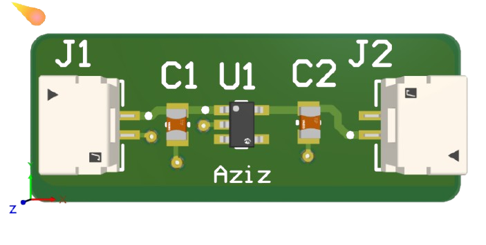
- Figure 2: PCB Bottom View

Documentation & Downloads
Gerber Files Download ZIP
Applications
- 3.3V supply for ESP modules, sensors, and logic circuits
- Prototyping and low-power IoT devices
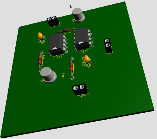
Second-Order System Response Prototype
This project features a custom PCB designed to demonstrate the dynamic behavior of a second-order system, commonly studied in control systems theory. It is used in university lab sessions to analyze step responses via oscilloscope observation.
Key Features
- Two operational amplifiers configured to simulate a second-order response
- Adjustable parameters:
- Gain (K) and damping ratio (ξ) via onboard potentiometers
- Input/Output interface:
- Step input applied through a connector (Ve)
- Output observed from Vs using oscilloscope probes
- Power supplied via +VCC, −VCC, and GND
-
Connector-based wiring for easy lab integration and oscilloscope connection
PCB 3D View
- Figure 1: PCB Top View
- Figure 2: ASsmebled PCB Top View
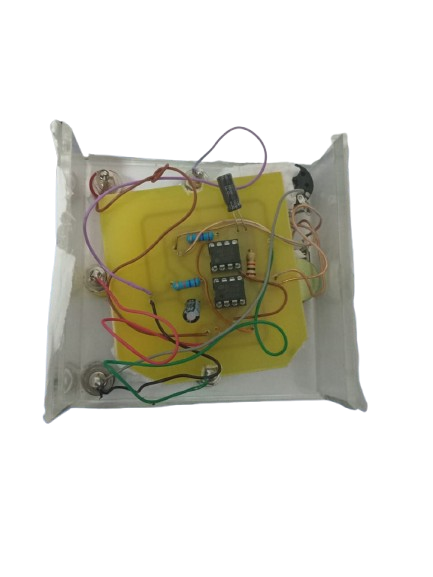
- Figure 3: PCB inside enclosure View

-
Applications
- Academic demonstrations of system response to a step input
- Control systems practical training
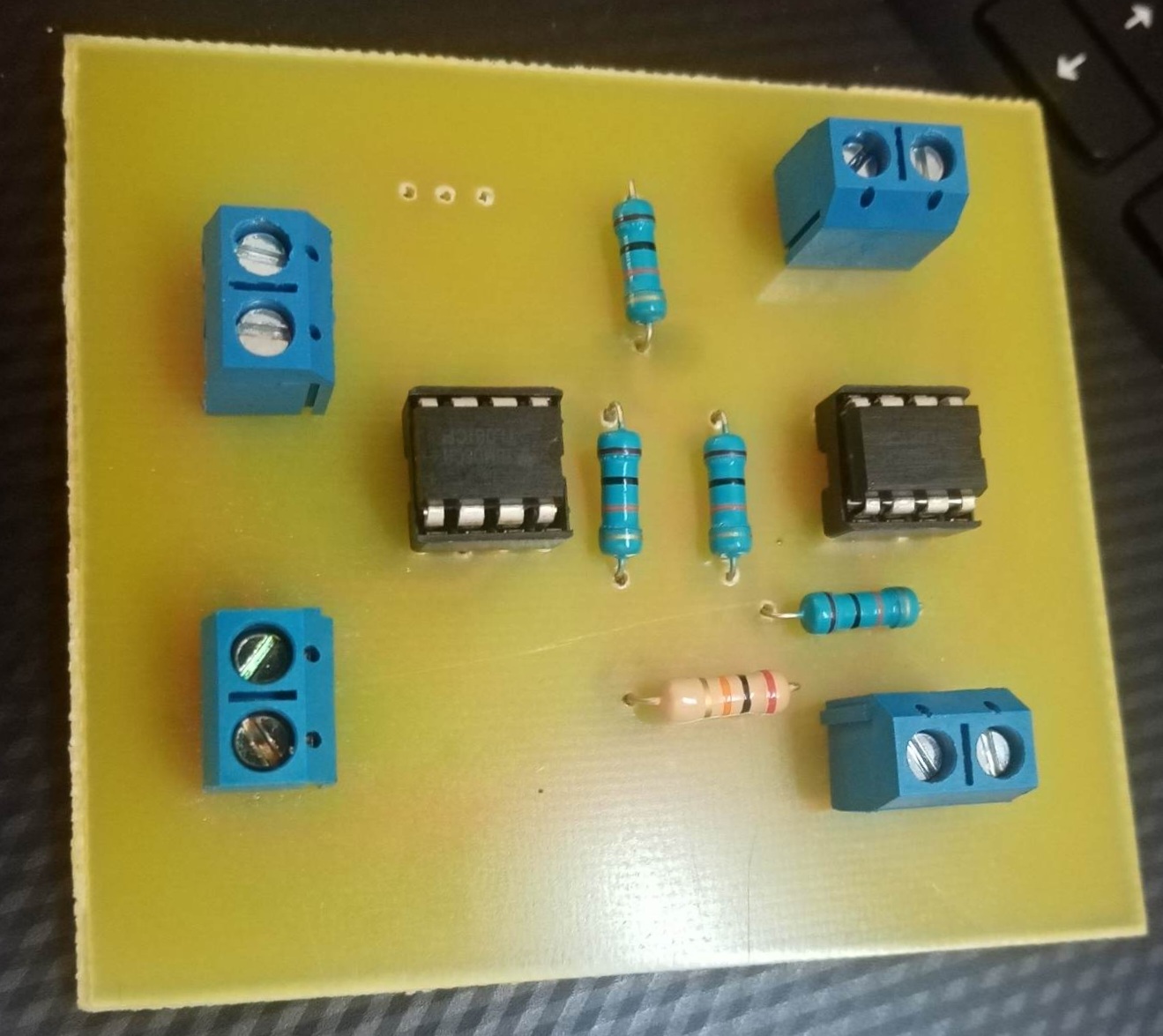
±5V to 0–5V Analog Signal Conditioning Module
This PCB is designed to adapt an input range of [−5V ; +5V] to a microcontroller-compatible range of [0V ; 5V]. It is used to command a first-order system using an Arduino UNO’s digital-to-analog output, providing a safe and usable analog signal.
Key Features
- Dual op-amp design for signal adaptation and level shifting
- Voltage regulators:
- LM7805 provides stable 5V output
- Input/output range conversion:
- Converts bipolar ±5V signal into unipolar 0–5V range
- Designed for Arduino-based system control
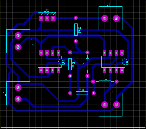
PCB 2D View
- Figure 1: PCB Top View
- Figure 2: ASsembled PCB Top View
Documentation & Downloads
Printing with PDF Files Download PDF
Applications
- Step response input conditioning
- Safe analog interfacing with Arduino and acquisition systems